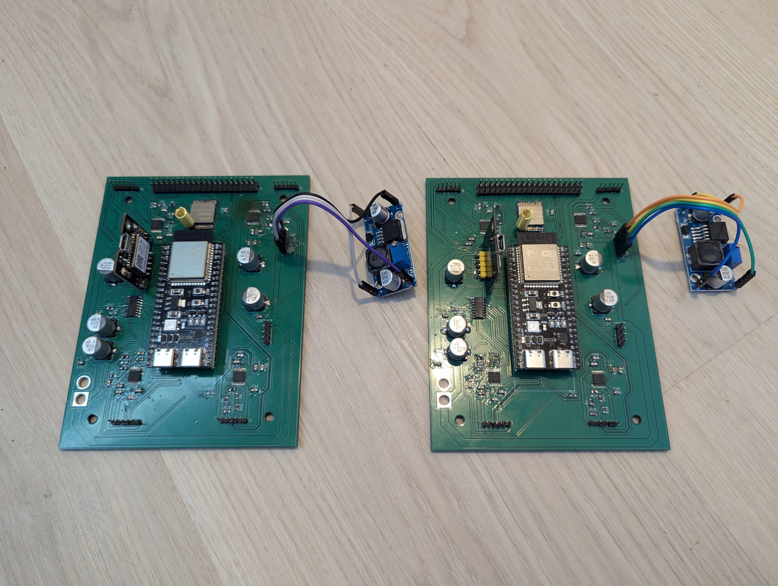
ESP32 Carrier board with quad h-bridges for mecanum drive
My Senior Design Project Mecanum Rover
Included are all my notes and designs for the senior design team project for which I was responsible for all hardware and microcontroller firmware

Overview
The included notes and files contain all the work I personally did for my senior design project. The goal was to create an autonomous rover that could use a combination of GPS and computer vision to navigate safely and analyze its environment. As the only EE major in our team of five, I was in charge of all hardware as well as the low level firmware. I have included in this section my PCB designs, design notes detailing how everything fits together, Arduino and C++ firmware, and photos of our completed project.
Not included is the higher level code for any tasks involving computer vision, LLM integration, or navigation/decision making. I had no involvement in that side of things, and honestly have little understanding of it.
A note about mecanum drive technology
Mecanum drive systems achieve omnidirectional motion by using four independently driven wheels fitted with passive rollers mounted at approximately 45 degrees to each wheel’s plane of rotation. Because each roller can rotate freely along its own axis, the traction force generated at the wheel–floor contact point is resolved into longitudinal and lateral components rather than acting purely in the wheel’s forward direction. In the conventional “X” roller arrangement, the lateral components from opposing wheels either cancel or reinforce depending on the commanded wheel directions. Driving all four wheels forward at equal speed produces pure longitudinal translation; reversing the wheels on one diagonal relative to the other produces lateral translation; and driving the left and right wheel pairs in opposite directions produces rotation about the chassis center. Arbitrary planar motion is generated by superimposing these three components, allowing the vehicle to translate with body-frame velocity (v_x), strafe with velocity (v_y), and rotate with angular velocity omega_z simultaneously.
For a rectangular chassis with wheel radius (r), half-length (Lx), and half-width (Ly), the inverse kinematic transformation converts the desired chassis velocity into individual wheel angular velocities. Under one common wheel-numbering and sign convention, these are omega_1 = (Vx-Vy-(Lx+Ly)\omega_z)/r, omega_2 = (Vx+Vy+(Lx+Ly)\omega_z)/r, (omega_3 = (Vx+Vy-(Lx+Ly)\omega_z)/r, and omega_4 = (Vx-Vy+-(Lx+Ly)\omega_z)/r. Each wheel is normally regulated by its own closed-loop velocity controller using encoder feedback, while a higher-level controller computes Vx, Vy, and Omega from desired trajectory. Because mecanum motion depends on controlled wheel-speed ratios rather than mechanical steering geometry, speed saturation must be handled by scaling all four wheel commands proportionally; independently clipping one wheel distorts the commanded motion vector. Real systems also require acceleration limiting, wheel-speed PID control, encoder-based odometry, and often inertial or external position feedback, since roller slip, unequal wheel loading, floor irregularities, and imperfect roller geometry make open-loop lateral motion substantially less accurate than forward motion.

Rover PCB and Control System Overview
Architecture Summary
The rover’s control electronics are split between:
A Raspberry Pi (high-level)
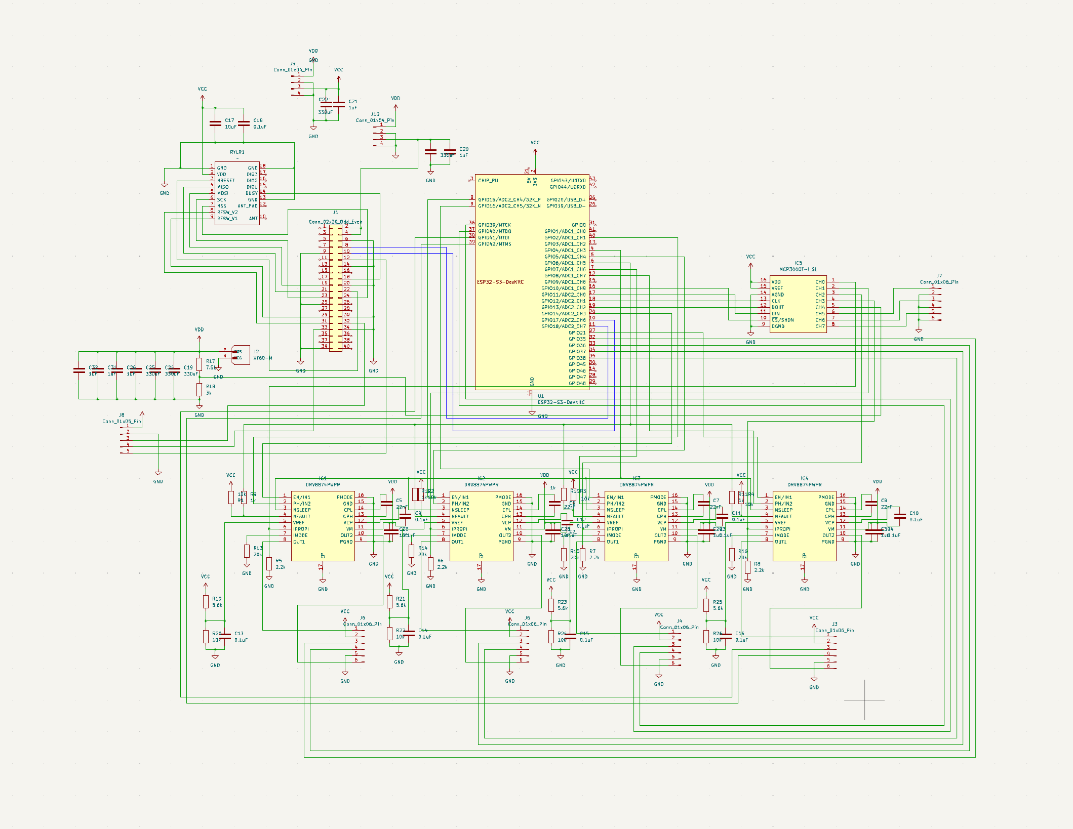
An ESP32 (low-level control) on custom PCB with all peripherals
They communicate through a UART link (TX/RX + GND) on the Pi’s GPIO header using simple text-based messages (CSV/command lines).
Raspberry Pi Responsibilities (High-Level)
The Pi runs all heavy logic and computer-vision software, possibly aided by processing on WiFi connected laptop.
Handles:
Vision and navigation (deciding where to go)
Path-planning and high-level decisions
Commanding motion goals as:
Linear velocity (v, m/s)
Angular velocity (ω, rad/s)
Collecting telemetry from the ESP32 for logging
Optional GPS + LoRa WAN (connected directly to Pi via UART4 and UART5)
Interface to ESP32:
Sends commands like
SET_VW,<v>,<omega>\nReceives telemetry lines at ~50 Hz:
TLM,<timestamp>,x,y,theta,v_meas,w_meas,w1..w4,I1..I4,faultsWatchdog: if no SET_VW received within 150 ms, ESP32 stops safely.
ESP32 Responsibilities (Low-Level)
The ESP32 handles all real-time control and motor timing.
Functions:
Drives 4 motors via H-bridge ICs (probably will use DRV887x family of chips)
Outputs: 4 × PWM (20 kHz) + 4 × DIR
Reads 4 quadrature encoders (A/B per wheel) using PCNT units
Runs 4 PID velocity loops @ 1 kHz
Computes odometry (x, y, θ) @ 100 Hz
Monitors driver nFAULT pins
Samples motor currents through an optional MCP3008 SPI ADC
Sends telemetry to the Pi @ 50 Hz
Executes watchdog / E-stop locally (no Pi needed to brake)
MCP3008 10-Bit ADC (Optional, future-use)
Connected to ESP32 via SPI (3.3 V)
Channels 0–3 → motor current sense amps (INA181)
Channels 4–7 → spare (battery, 5 V rail, temperature)
Can be enabled in firmware with #define
ENABLE_MCP3008 1
Power Supply Considerations
This board will accept power through a single XT60 connector from an 11.1V battery pack
That voltage will be fed unregulated, but filtered by capacitors, to all four H-bridges
A step-down SMPS on a daughter board will provide 5v to the Pi through the ribbon cable
A second SMPS will be tuned to provide 3.3V for the ESP32 any other peripherals that need it.
GPS and LoRa Modules (Pi-side)
GPS on UART4 (GPIO8 TX, GPIO9 RX, PPS → GPIO4)
LoRa on UART5 (GPIO5 TX, GPIO6 RX)
Both communicate directly with the Pi (not through ESP32)
Shared ribbon cable carries all GPIO lines and grounds
UART Assignments (Pi GPIO Header)
|
Peripheral |
Pi GPIOs |
Description |
|---|---|---|
|
ESP32 Link |
14 TX, 15 RX |
main command/telemetry UART0 |
|
GPS |
8 TX4, 9 RX4, 4 PPS |
NMEA + 1 Hz pulse |
|
LoRa |
5 TX5, 6 RX5 |
telemetry radio |
|
Ground lines |
multiple |
interleaved for signal return |
All are 3.3 V TTL, short single-ended lines in one ribbon cable.
Motor/Encoder Connections (ESP32-side)
|
Function |
Qty |
Notes |
|---|---|---|
|
PWM outputs |
4 |
LEDC 20 kHz |
|
DIR outputs |
4 |
digital |
|
Encoder A/B |
8 |
PCNT quadrature |
|
nFAULT inputs |
4 |
active-low |
|
Current sense |
Via SPI |
via INA181 → MCP3008 |
|
Supply bus |
5/3.3V |
shared with Pi buck converter (5 V out) |
Control Flow
Pi computes desired velocities (v, ω) from vision/navigation.
Sends SET_VW,v,ω to ESP32.
ESP32 converts to per-wheel setpoints via skid-steer kinematics.
Encoders measure actual speed → PID adjusts PWM duty.
ESP32 updates odometry & samples current.
Sends telemetry back to Pi for logging/fusion.
If comms lost or fault detected → ESP32 ramps PWM → 0.
Firmware Summary (ESP32 / Arduino)
Written entirely in Arduino due to my familiarity.
Uses:
LEDC for PWM
PCNT for encoder counting
HardwareSerial for Pi UART
Optional SPI for MCP3008
Inner PID loop @ 1 kHz (FreeRTOS-friendly)
Telemetry @ 50 Hz CSV
Modular: future features (e.g., current limiting) added via code later.
System Behavior
Pi = high level reasoning → “where & how fast?”
ESP32 = low level control → “make wheels smoothly at desired speed and acceleration”
Clean separation:
Pi handles perception, mapping, mission logic.
ESP32 guarantees smooth motion, real-time monitoring, ensures that the Pi doesn’t have to expend CPU overhead performing precise timing tasks.
My Memo to My Team Regarding Hardware Integration
“I want to give everyone a clear picture of where the Pi-side LoRa/GPS system currently stands, what pieces are already implemented, what decisions we still need to make together, and what components need to be developed on the Pi side.
This should help us synchronize our work with the Heltec (the ESP32 based LoRa module Perry gave us) and the linked Python based PC interface I’m developing and ensure everything lines up cleanly when we integrate everything together. As I mentioned before, this should all be treated as an optional extra for our project.
To clarify at the top, they LoRa WAN module on the Rover is not the same as the one at the base station.
The rover has a Reyax RYLR689 module which internally has the LLCC68 chip and is connected to the Pi via SPI and some other data lines.
The base station uses the Heltec WiFi_LoRa_32_V2 module, which consists of an ESP32 and an SX1276 LoRa chip on the same board. This makes writing code for the base station side of things easy, it just needs a single arduino script for the ESP32, and a python script running on the PC. That is mostly done already. The board file to write Arduino code successfully to the module is found here:
https://resource.heltec.cn/download/package_heltec_esp32_index.json
1. What is Already Written and Working
1.1 Hardware Abstraction Layer (HAL) – Complete
I already have a complete C++ hardware abstraction layer, deposited in the Github page, for the Raspberry Pi that handles:
LoRa (LLCC68 module) — board::LoraRadio
SPI configuration (spidev0.0)
BUSY line monitoring
RESET control
RF switch control (V1/V2 → RX/TX/Sleep)
Safe SPI transfers with BUSY synchronization
A basic “status” probe using a dummy opcode
Important:
This layer does not implement LoRa configuration, packets, modulation, or any radio protocol.
It only exposes low-level access to the LLCC68 chip. This code should not be touched unless absolutely necessary, and at any rate the hardware and pin-out choices therein are set in stone.
GPS (GT-U7 module) — board::GpsReceiver
Initializes the correct UART port (UART5 on GPIO12/13)
Sets raw serial mode at the configured baud rate (default 9600)
Provides non-blocking NMEA line reads
Returns one NMEA sentence at a time as a std::string
Again, this is a transport-level abstraction only.
It does not parse NMEA sentences into numerical latitude/longitude or anything structured.
PC & Heltec Side — Complete
I have already developed:
Heltec WiFi LoRa 32 V2 firmware (Arduino)
Configures the SX1276 radio for 915 MHz LoRa
Acts as a USB <-> LoRa text bridge
Anything typed on the PC is sent as a LoRa packet
Anything received over LoRa is forwarded as text over USB
Python command-line tool
Automatically detects the Heltec’s COM port
Opens a terminal-like interface
Sends/receives newline-terminated text messages
Displays incoming LoRa messages with timestamps
This provides the other end of the link and lets us chat via command line. I can modify this code as needed.
2. What We Must Decide Together
To ensure the Pi and Heltec can talk to each other reliably, we need to agree on two things:
2.1. LoRa Radio Parameters (must be identical on both ends)
I’m proposing the following defaults for U.S. operation:
Frequency: 915 MHz
Bandwidth: 125 kHz
Spreading Factor: SF7
Coding Rate: 4/5
Preamble: 8–12 symbols
Header Mode: explicit
CRC: enabled
Sync Word: LoRa default (0x34) unless we want our own
These are compatible with the two modules: SX1276 (Heltec) and the LLCC68 (Pi).
2.2. Text-Based Message Format (our “wire protocol”)
Everything exchanged between Pi ↔ Heltec ↔ PC will be plain text.
We need a shared format for:
Telemetry from Pi → PC
Examples:
GPS,<lat>,<lon>,<alt>,<fix>STAT,<uptime>,<sats>,<hdop>,<battery>
Commands from PC → Pi
Examples:
CMD,PINGCMD,REQ_FIXCMD,SET_RATE,1Hz
Once we finalize these message structures, I’ll update the Heltec/Python side to enforce or help format them.
3. What Must Be Written by the Rest of the Team
Now that the HAL is in place, everything above it needs to be designed and implemented by the rest of the team. My knowledge here is limited, and I no longer have any hardware for testing.
Here are the components you’ll need to build:
3.1. Full LLCC68 Radio Driver (C++)
board::LoraRadio only gives raw SPI access.
You must implement the LLCC68 operational layer, including:
SetStandby, SetRx, SetTx
SetRfFrequency(915MHz)
SetModulationParams (SF7/BW125kHz/CR4/5)
SetPacketParams
WriteBuffer (TX FIFO)
ReadBuffer (RX FIFO)
IRQ handling (at least TX done / RX done)
Timeouts / error recovery
In short:
Everything needed to actually transmit & receive LoRa packets.
My Heltec side is already doing the equivalent for its different SX1276 chip, so your module just needs to match it.
3.2. GPS NMEA Parser (C++)
board::GpsReceiver gives you raw NMEA strings.
You need to:
Parse $GPGGA and $GPRMC at minimum
Produce something like:
struct GpsFix {bool valid;double latitude;double longitude;double altitude;int num_sats;};
Provide a function to get the latest valid fix
You do not need to worry about delivering this to me; just embed it into the Pi application logic.
3.3. Application Logic (C++)
This is the part that ties everything together.
Responsibilities:
Send telemetry
Poll GPS
Build a text line using our agreed format
Send over LoRa using your LLCC68 driver
Receive commands
Listen for incoming LoRa packets
Parse text commands
Respond appropriately (e.g., send GPS fix on demand)
Persist and handle system state
Reporting interval
Ping/Pong
Any additional features your side wants to include
This is essentially the logic that places the Pi in “the field,” broadcasting telemetry and reacting to commands sent from the PC interface.
4. Integration Path
Once the Pi team has:
A working LLCC68 driver
A working NMEA parser
A simple main loop sending and receiving our text messages
Then everything will tie together seamlessly:
I can send commands via the Python terminal
Those commands travel to Heltec module over USB/COM port, then via LoRa link to the Pi’s LLCC68 driver
The Pi responds via LLCC68 → Heltec → Python CLI
This will give us a clean, testable communication loop.
5. Summary
Already done (by Charlie):
LLCC68 hardware abstraction (SPI/GPIO/RF switch)
GT-U7 serial abstraction (line-based NMEA)
Heltec SX1276 firmware (USB↔LoRa bridge)
Python terminal interface (auto-detects COM port)
We must agree on:
LoRa radio parameters (915 MHz, SF7, BW125kHz, etc.)
Text message protocol (GPS format, command format)
Pi team must implement:
Full LLCC68 radio driver
GPS NMEA parser
Application layer (telemetry + command handling)”
Python Code
Lorem Ipsum
Arduino Code
Lorem Ipsum