
hard wired home automation with automotive can bus
CAN Bus Home Automation and Plant Care
A single daisy chained network to monitor and water my plants and control my blinds.
How I Began
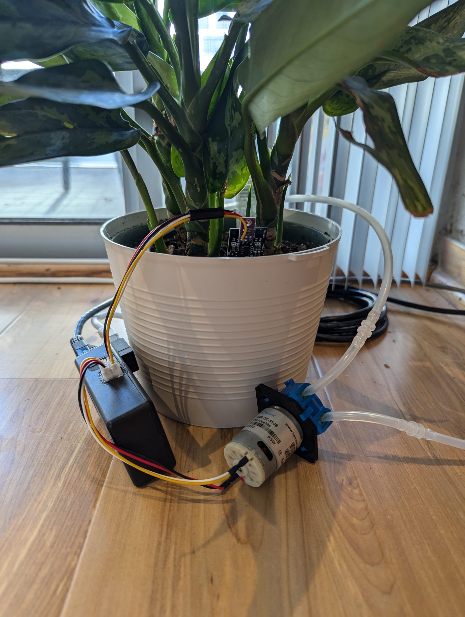
In the spring of 2026 I started a new job designing the electrical systems for firetrucks. This reintroduced me to the CAN bus standard, something that I already had some experience with through one of its derivatives, NMEA 2000, used in the marine field. I wanted to develop a personal project that would give me more experience with this communication protocol, and by way of finding a solution looking for a problem, decided to make a hardwired system that would monitor and water my plants. I later decided to add additional nodes that would open and close the blinds in two rooms, and integrated it into my already existing lighting automation system, the details of which can be found on another page.
Some Background on CAN Bus
Controller Area Network, or CAN, is a multi-master serial communication standard designed for reliable data exchange among distributed electronic nodes in noisy environments. In terms of the OSI model, classical CAN really only defines the physical and data-link layers. The physical layer specifies differential signaling over the CAN High and CAN Low conductors, while the data-link layer defines frame structure, bus arbitration, error detection, acknowledgement, and retransmission behavior. CAN itself does not define a complete network or application layer; protocols such as SAE J1939, used in vehicle and engine systems provide higher-level addressing, device profiles, and message conventions.
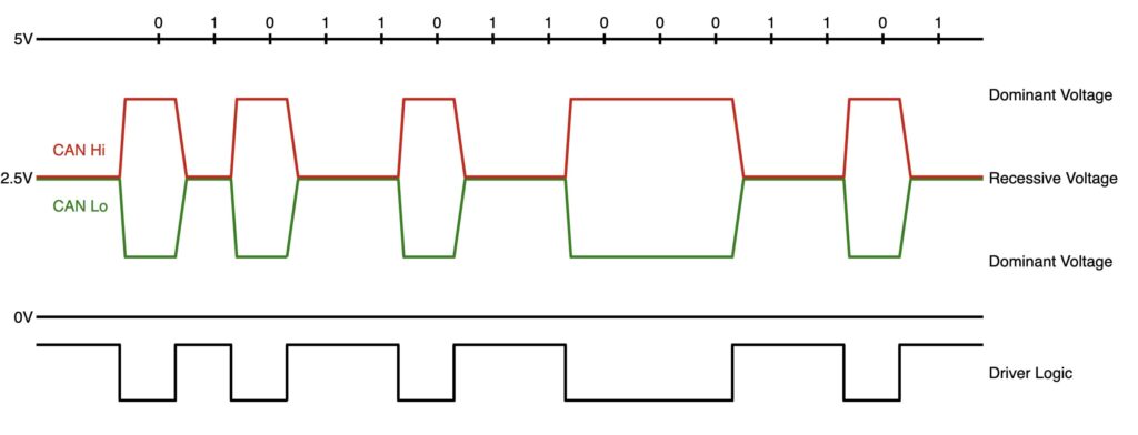
CAN uses a shared broadcast bus in which transmitted frames are identified by message identifiers rather than by explicit source and destination addresses. Every node receives each valid frame and decides whether the identifier is relevant. The identifier also establishes message priority during arbitration. If multiple nodes begin transmitting simultaneously, CAN performs nondestructive bitwise arbitration, with dominant bits overriding recessive bits on the bus. The frame with the numerically lowest identifier continues transmitting, while lower-priority nodes stop and retry later without corrupting the winning frame or consuming an additional arbitration cycle.
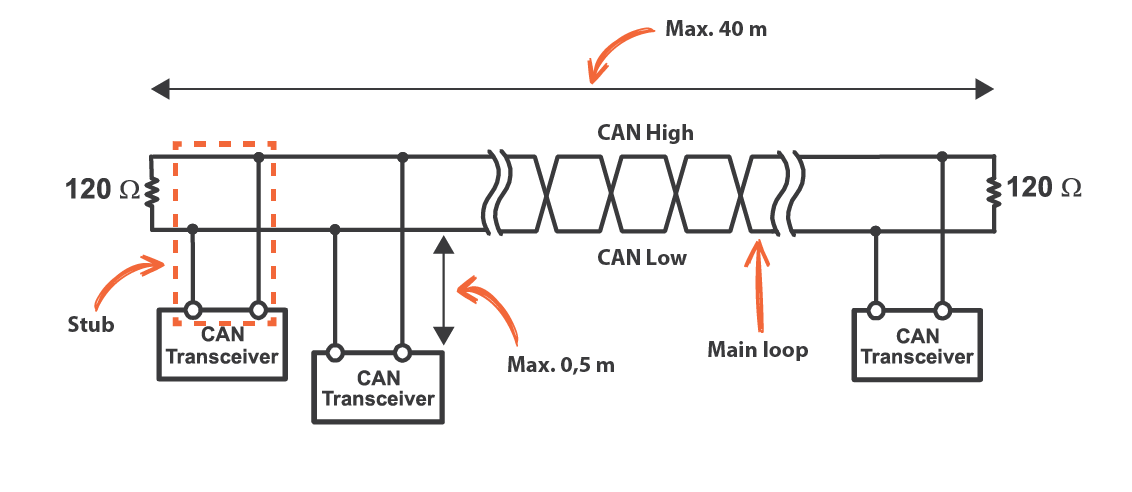
The physical bus is normally constructed as a linear twisted pair with a 120-ohm termination resistor installed at each end of the main trunk. Differential signaling provides strong common-mode noise rejection, while proper termination minimizes reflections. A controller creates and validates frames, performs arbitration, calculates cyclic redundancy checks, and manages error counters, while a transceiver converts logic-level transmit and receive signals into the differential signals on the bus.
System Architecture
My system consists of six nodes, including the Raspberry Pi at one end, three plant monitoring and watering nodes, and two stepper motor nodes for opening and closing my blinds. There is of course the option to add more as needed.
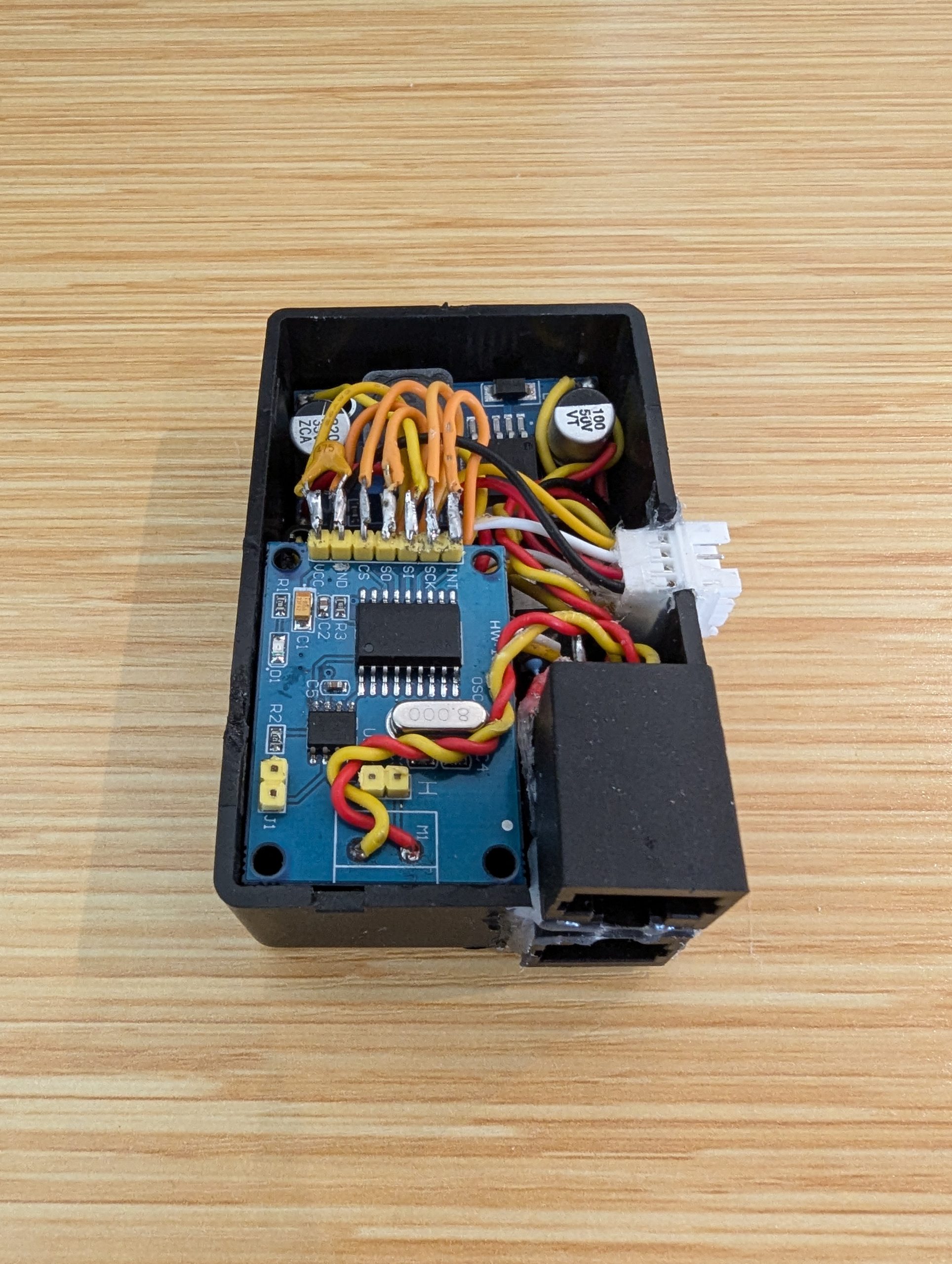
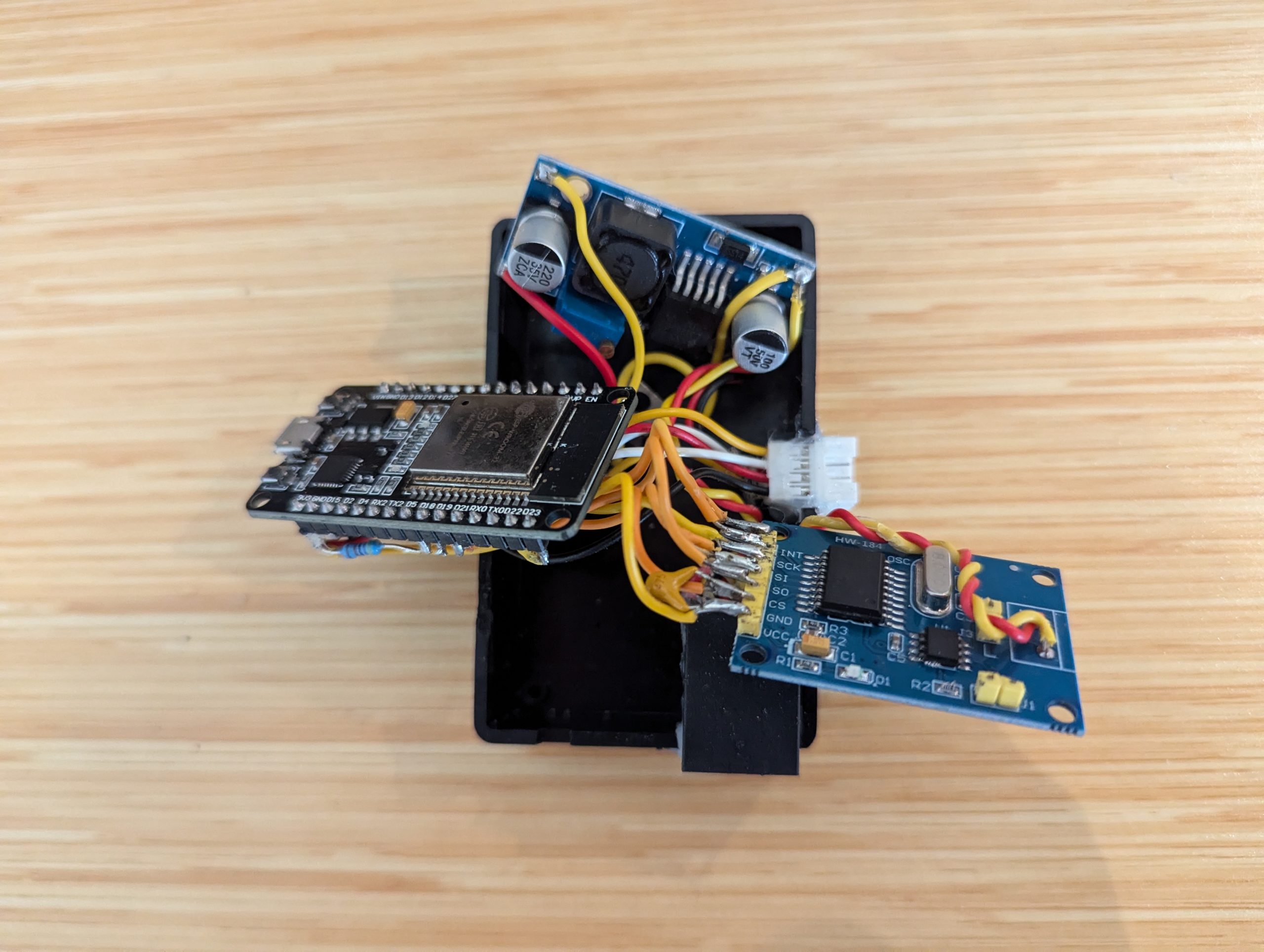
Each node, apart from the Pi at one end, consists of a standard classic model esp32 dev module, a MCP2515 CAN transceiver module, which accepts a 3.3v logic supply and handles the conversion between the single ended full duplex TTL that the microcontroller is accustomed to and the differential half duplex CAN communication, and an adjustable buck converter module to convert 12V from the supply to 5V. The esp32 dev module’s onboard regulator converts that to 3.3v for the transceiver and everything else.
The three plant monitoring nodes incorporate an N-channel mosfet for low side switching of the peristaltic watering pump, and connections for the soil moisture and ambient light sensors. These analog sensors just output a 0-3.3v signal proportional to moisture or light, so some experimenting was necessary to assign thresholds and qualitative values to those otherwise meaningless 12 bit number stream.
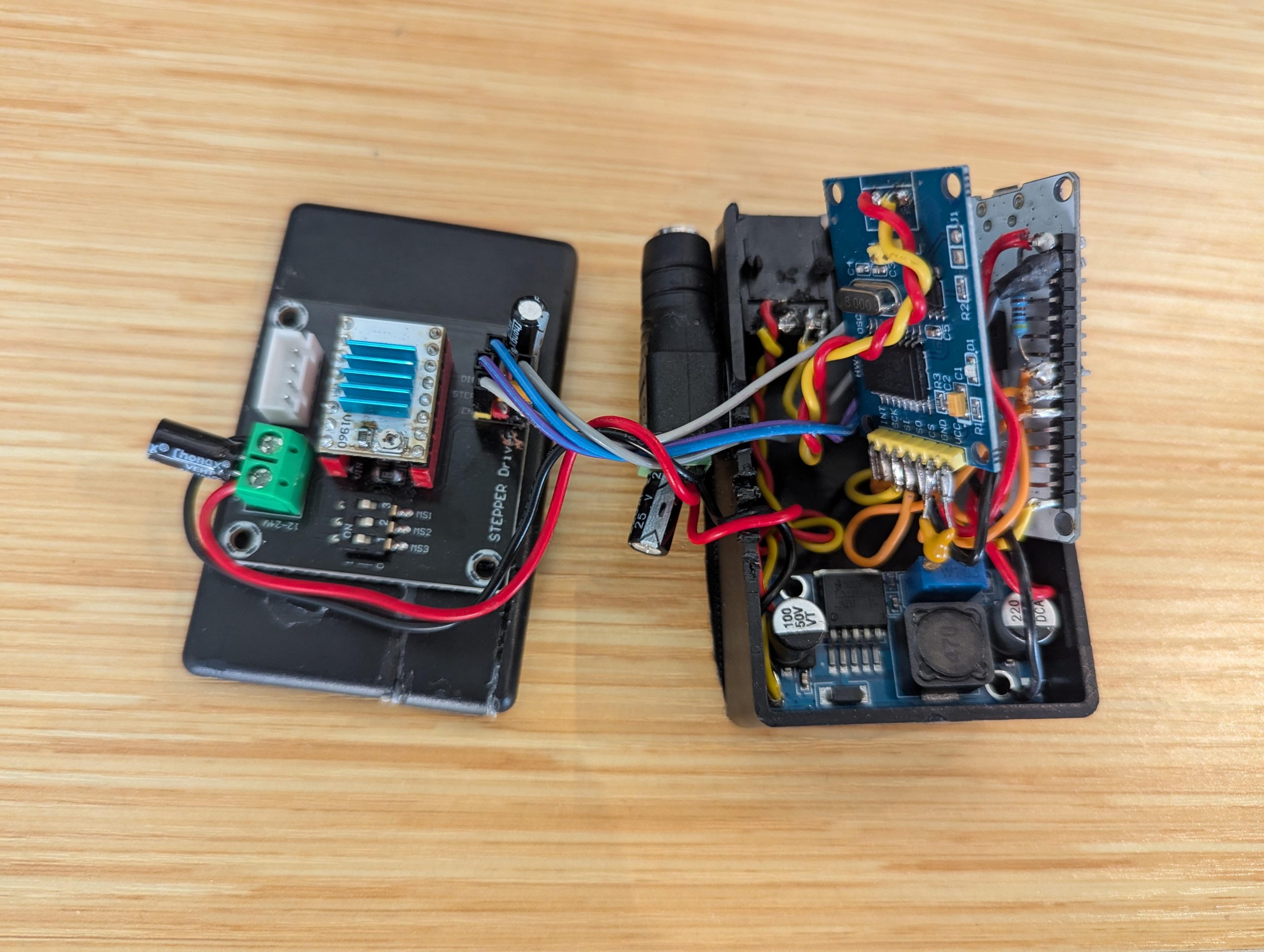
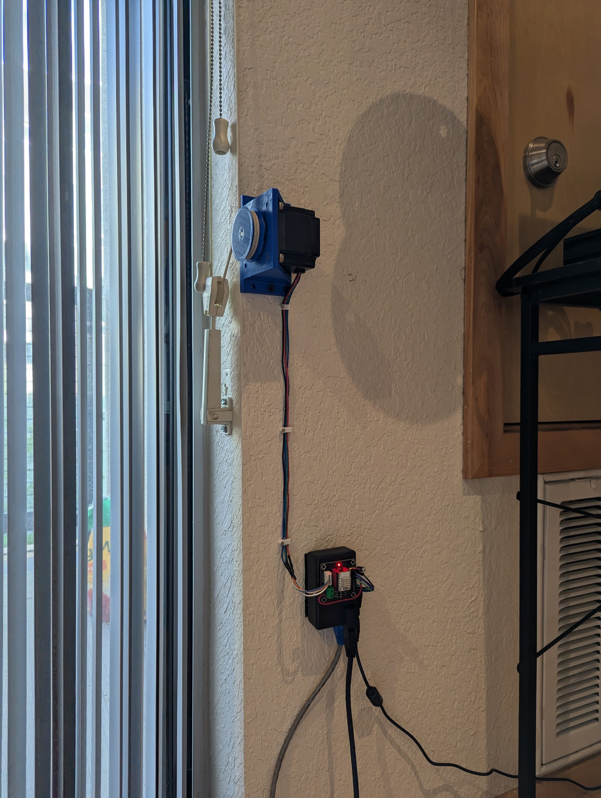
The two stepper motor nodes feature a TB67S109 stepper motor driver breakout board and connections for two end-stops. The TB67S109 chip was the only easily sourced stepper driver I could find that could both accept 3.3V logic inputs and handle 4A loads. Typically smaller stepper drivers found in 3D printers and such are limited to 2.5A, and the larger ones for industrial applications expect 5V logic. This model was a lucky best of both worlds for my project. The pulleys for the blind cords were 3D printed and arranged in such a way that no holding torque is required. This means that after moving to a desired position the driver enable line can be deactivated to prevent potential overheating.
Both CAN communication and DC power is delivered by standard CAT6 ethernet cabling, with a single pair for data and three pairs grouped together for power. Either end of the data bus is terminated with 120 ohm resistors, which both matches the CAN standard, and more or less matches the 100 ohm characteristic impedance of Cat6 cabling. Realistically, at the frequencies I am operating at mismatch or noise should not be much of a problem. While 12 volts passed over ethernet is sufficient for the plant watering nodes as they only require only a few hundred milliamps to function even when the pump is running, as well as the logic portion of the stepper motor nodes, the stepper motor drivers themselves, running at 3A, require isolated 12V wall supplies.
Module Pinouts
Pinout for Legacy ESP32 Plant Watering and Monitoring Nodes:
|
Function |
ESP32 GPIO |
Notes |
|---|---|---|
|
Water level analog input |
GPIO25 |
|
|
Ambient light analog input |
GPIO33 |
|
|
Motor PWM output |
GPIO32 |
safe PWM pin |
|
CAN SPI MOSI |
GPIO23 |
VSPI MOSI |
|
CAN SPI MISO |
GPIO19 |
VSPI MISO |
|
CAN SPI SCK |
GPIO18 |
VSPI clock |
|
CAN SPI CS |
GPIO5 |
strapping pin, add pull-up |
|
MCP2515 INT |
GPIO27 |
interrupt input |
Pinout for Legacy ESP32 Blind Motor Node:
|
Function |
ESP32 GPIO |
Notes |
|---|---|---|
|
CAN SPI MOSI |
GPIO23 |
same as my legacy plant nodes |
|
CAN SPI MISO |
GPIO19 |
same as my legacy plant nodes |
|
CAN SPI SCK |
GPIO18 |
same as my legacy plant nodes |
|
CAN SPI CS |
GPIO5 |
strapping pin, add pullup |
|
MCP2515 INT |
GPIO27 |
same as your existing legacy-node convention |
|
Endstop input |
GPIO33 |
regular GPIO, supports pull-up |
|
DRV8825 STEP |
GPIO25 |
output |
|
DRV8825 DIR |
GPIO26 |
output |
|
DRV8825 nENBL |
GPIO32 |
output |
|
DRV8825 nSLEEP / nRESET |
NA |
output, tied together on board |
Python Code
Lorem Ipsum
Arduino Code
Relatively simple firmware. Both versions share more or less the same CAN interface code. The plant watering nodes add in two 12-bit analog readings for soil moisture and ambient light, and a single PWM output for the peristalic pump. The blind motor nodes include code for opperating a single stepper motor (step, direction, and enable signals) and two digital inputs for endstops.