
An Exploration of Modern Digital Modulation
Point to Point QAM Modems
Bidirectional Text Communication Over 16-Point QAM in the KU-Band using discarded obsolete VSat hardware
How This All Started
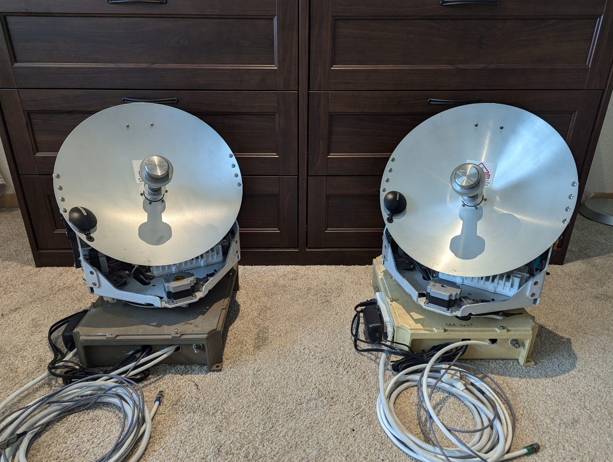
I worked in the marine electronics field for a while during a transitional time in the industry when a lot of traditional geostationarly satelite downlinks were being ripped off of vessels and replaced with newer much more capable Starlink systems that are not bound by the long latency and relatively low data rate of older marine broadband systems. While the advent of Starlink was disappointing for the business I worked at, It did give me an opportunity to acquire some hardware that when first sold cost thousands or even tens of thousands of dollars. I chose to repurpose some of it to attempt to build QAM modems, the foundational technology behind WiFi, at the most basic bare bones level. The following will cover the topology of my two identical modems that with different local oscillator frequencies, are capable of full duplex digital communition on the kilobit range.
Discussion of Theory
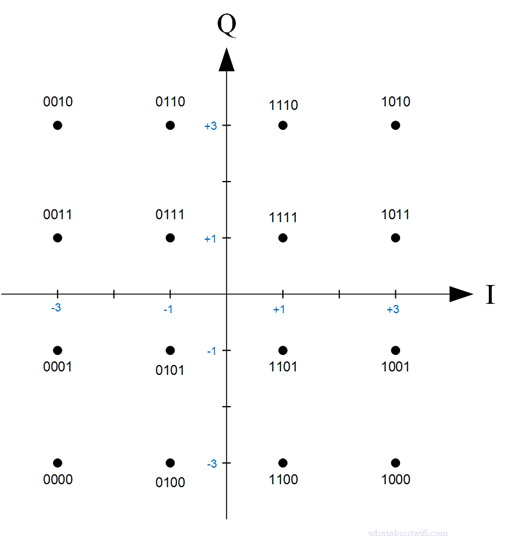
Quadrature amplitude modulation transmits information by independently controlling the in-phase and quadrature components of a carrier. The transmitted waveform can be expressed as s(t)=I(t)cos(2pi*fc*t)-Q(t)sin(2pi*fc*t)), where the cosine and sine carriers are orthogonal and can therefore carry separate amplitude values in the same frequency channel. In 16-QAM, the (I) and (Q) components each assume one of four nominal levels, conventionally (-3,-1,+1,) or (+3), producing a square constellation of 16 possible points. Each point represents one symbol and carries four bits. Gray coding can used so that neighboring constellation points differ by only one bit, reducing the number of bit errors produced by an incorrect nearest-neighbor decision.
The mapped symbols are passed through pulse-shaping filters, normally root-raised-cosine filters, before being converted into analog (I) and (Q) waveforms and applied to a quadrature modulator. Pulse shaping limits occupied bandwidth and allows successive symbols to overlap without producing intersymbol interference at the correct sampling instants. For a symbol rate Rs) and roll-off factor (\alpha), the ideal raised-cosine RF bandwidth is approximately ((1+\alpha)R_s), while the uncoded bit rate is (4R_s). Because 16-QAM carries information in both amplitude and phase, the transmitter must preserve the relative positions of the inner and outer constellation points. DAC clipping, mixer imbalance, phase error, or power-amplifier compression directly distorts the constellation and increases the error-vector magnitude.
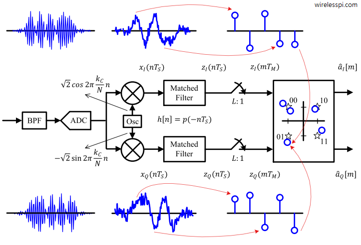
At the receiver, the RF signal is mixed with locally generated cosine and sine carriers to recover the baseband (I) and (Q) components. Matched filtering, automatic gain control, symbol-timing recovery, carrier-frequency and phase correction, and channel equalization are then applied before the signal is sampled once per symbol. Each received sample is compared with the 16 permitted constellation points, and the nearest point is selected; for an ideal unnormalized constellation, the independent (I) and (Q) decision thresholds are (-2,0,) and (+2). The selected point is converted back into four bits using the inverse Gray mapping. Noise, phase instability, timing error, multipath, and nonlinearity spread or displace the received points, and reliable communication depends on keeping these disturbances small relative to the distance between adjacent constellation points.
System Overview
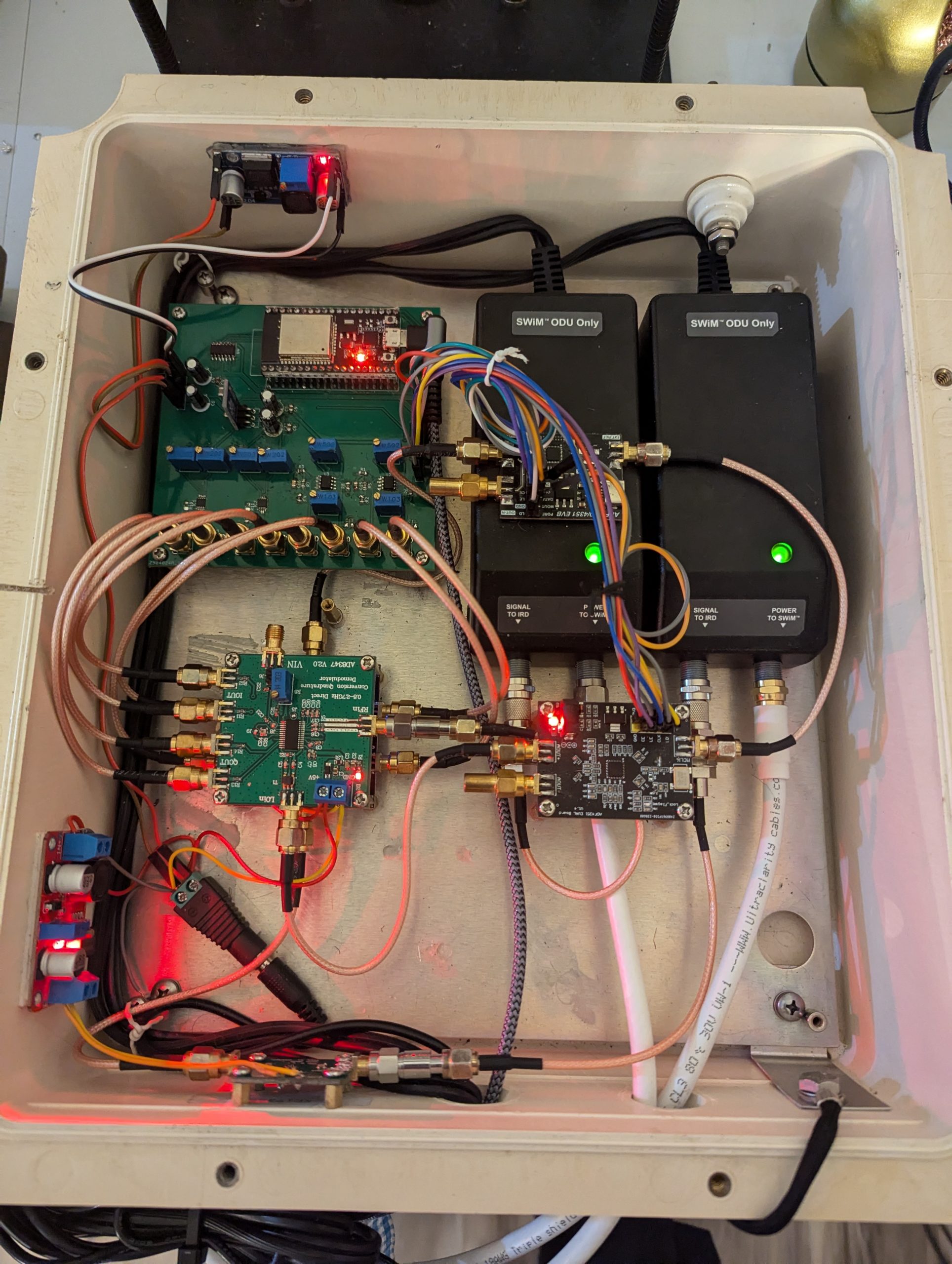
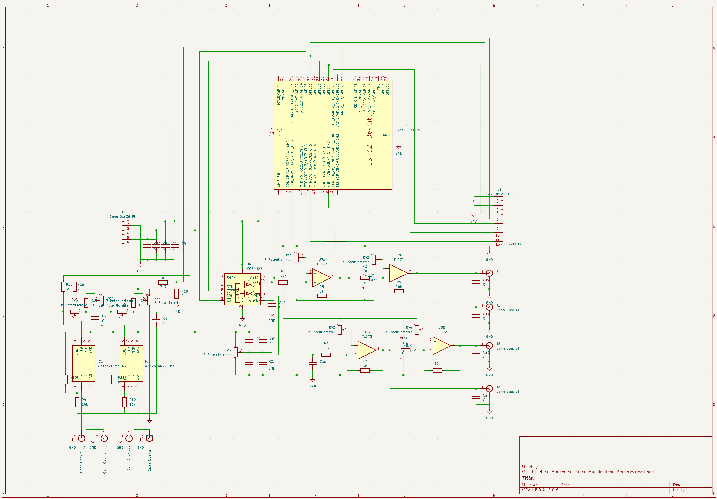
I chose an ESP32 as the heart of my two modems. I can program it in the Arduino language and it contains two 12 bit ADCs which simplifies things. On the transmission end, I chose a dual channel MCP4922 12-bit DAC which can be communicated with over SPI. The data rate over that communication protocol is fundamentally limited, and in practice the clock seems to be limited even further to about 2 MHz. However, for my purposes and for proof of concept, I believe it is sufficient. This DAC outputs two 12-bit numbers which represent sinusoids ‘s 90° apart. They are not fed directly into the modulator board. This ADL5375 modulator chip is designed to accept differential signals, but the output from the ADC is single-ended. This required the insertion of conversion circuitry to generate the appropriate differential signals of 1V peak-to-peak with an DC offset of 0.5V. This circuit consists of four op-amps, two for each the sin and cosine channels, with potentiometers for offset adjustment.
To set up two terminals I need two pieces of code on each end. On each end on a laptop connected via USB to the modem there is a python script running which opens a text window so that the user can enter their message, and when enter is pressed it is converted into QAM symbols, two for each ASCII character and sent via USB to the ESP32. An Arduino program running on the ESP32 converts between each 16 point QAM symbol in real time and determines the appropriate combination of cosine amplitudes and sends them along the SPI bus. When receiving it determines the QAM symbol that most closely matches what it is reading from the ADCs, and sends that back up the USB connection to the other laptop where the python code waits to convert it into ASCII and display it in a separate text box.
The QAM modulator board only produces an output power 0.5 dBm. This is insufficient to feed into my Block Up-Converter, and there is also a maximum input to the BUC of 13 dBm. The signal first feeds through a 30 decibel amplifier and then before passing through a 20 dBm attenuator. This is not the most efficient solution, but I had limited hardware options. The signal then feeds into the DC power inserter and finally into the BUC which transmits at 8 Watts. From this point it travels directly via line of sight from the parabolic reflector to the opposite and identical modem. On the receiving end the signal passes through another 20 dB attenuator before it travels into a AD8347 QAM demodulator board. After being converted back into baseband I chose to use AD8237 instumentation amplifiers. These offer adjustable gain and offset. With the appropriate potentiometer adjustments I am am able to produce a 3.2v peak-to-peak output wave to feed into the ADC inputs of my microcontroller. They also serve to convert the differential signal from the demodulator into a single ended signal for the ESP32’s to sample.
Both the modulation and demodulation chips require a local oscillator inputs, which set the tuning. These are generated by ADF4350 adjustable oscillator modules, which have a set frequency and power level programmed into them upon initialization by the same SPI bus that sends data to the DAC. These can generate a wide range of UHF frequencies and dictate the frequency the modulator multiplied by the baseband before it is further upconverted into the Ku band by the BUC, and allow the demodulator to do the same in reverse to restore the signal to baseband on the receiving end.
All of the circuitry requires a number of DC voltages that need to be produced and maintained at stable levels. Fortunately, both my BUC’s and LNB’s accept a pretty wide DC voltage. I used off the shelf power injectors originally meant for DirecTV’s SWM satellite systems. They output 21 volts which is well within the range of both the BUCs and LNBs. The ESP32 itself operates at a 3.3 volt logic level. I have an off the shelf buck converter which produces 3.5 volts which is within tolerances. This also powers the DAC and the local oscillator boards. The modulator and demodulator boards are powered straight from the main 5V supply. For the differential output from the op amps I require a negative voltage close enough to negative Vcc and that comes from charge pump inverter modules. Finally, the amplifier module that produces the 30 decibel amplification between the output of the QAM modulator and the power inserter requires 12 volts. This is done with an adjustable boost converter. This means in total I have five different voltage levels, 21 volts, 5 volts, ~negative 5 volts, 3.3 volts, and 12 volts.
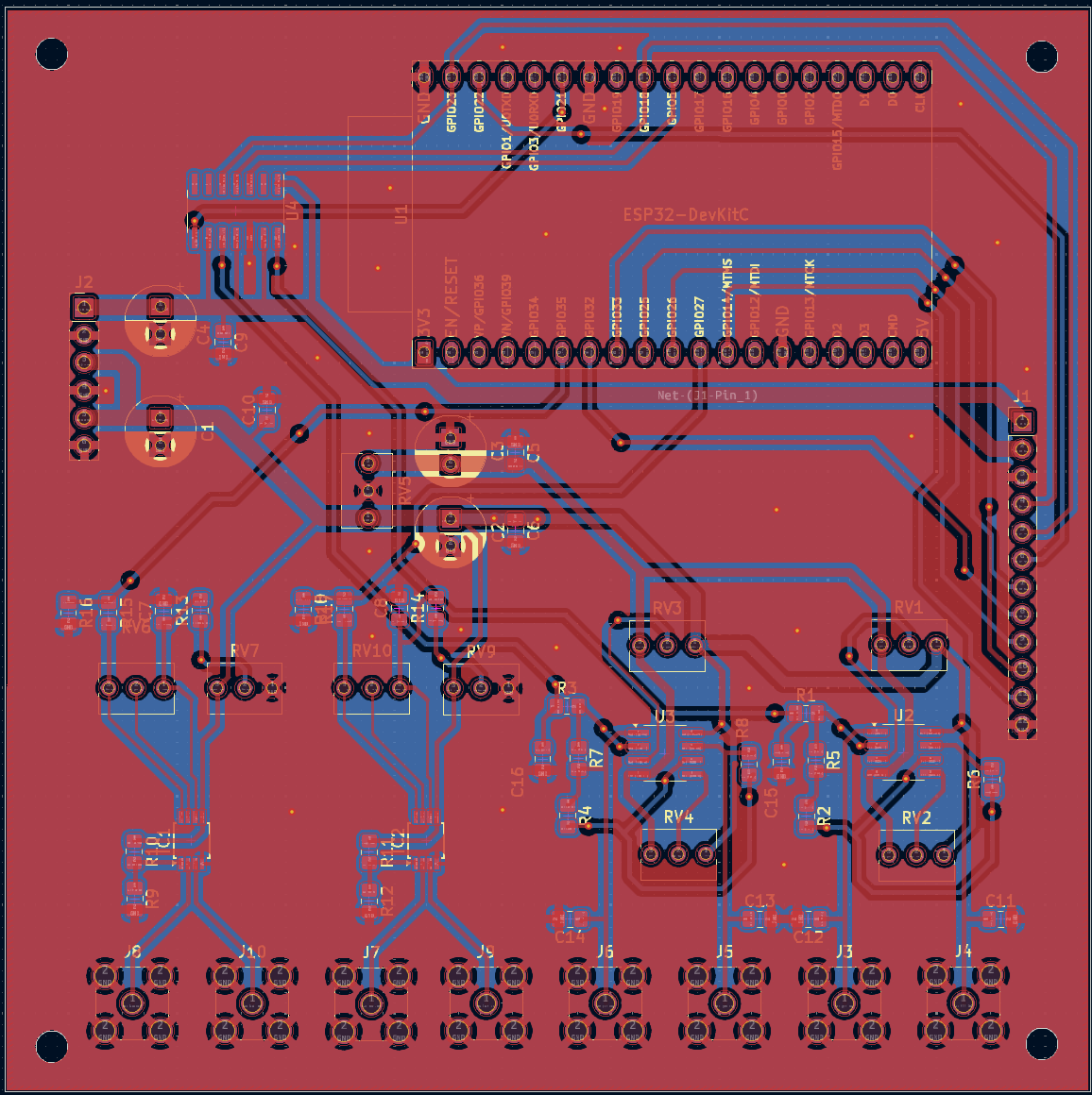
After verifying the functionality of my baseband section, I designed a PCB that I ordered from JLCPCB. My initial iteration was larger than it needed to be and did not include the instrumentation amplifiers. The next version included those instrumentation amps and pots that allow me complete control of the gain and offset, however I did not realize at the time that these IC’s open up the possibility of adding automatic gain control. This may be critical in all but the most controlled testing environments, and I hope to add that feature in the next revision.
Python Code
A single python script runs on laptops on either end and provides the user interface and performs higher-level data encoding and decoding. At the transmitting end, it accepts real time keyboard in put, converts each character into a sequence of standard ASCII bits, maps those bits to 16-QAM symbols, and sends the resulting symbol stream to the ESP32 over a serial connection. At the receiving end, it reads the detected symbols returned by the ESP32, reconstructs the original bit sequence, converts the data back into characters, and displays the recovered text. This division allows the computer to handle flexible data processing while the ESP32 manages the timing-critical interaction with the modem hardware.
Arduino Code
The ESP32 firmware performs all real time hardware control. On the transmitting side, it receives encoded symbol data from the computer over USB serial, converts each symbol into the corresponding in-phase and quadrature amplitude values, and writes those values simultaneously to the two channels of an MCP4922 digital-to-analog converter. It also controls the two local-oscillators and maintains the precise output timing needed to generate the QAM baseband waveform. On the receiving side, the firmware samples the analog (I) and (Q) outputs of the quadrature demodulator, determines which constellation point most closely matches each sample, and forwards the recovered symbol data to the computer.
Some potential issues remain, some more serious than others:
– This system may not include adequate filtering. I still get some noise out of my op amps even though I have plenty of filtering on the power rails. Curiously when I added 2.2 nF filter caps to the output it created instability and the output rang at about 20 kHz on its own. You can see on my board where I had to remove them.
– I am using 75 Ohm RG-6 cable and the BUC and LNB are also 75 Ohm but all other components in my modems are designed around a 50 ohm characteristic impedance. Off the shelf impedance matching hardware for those values is surprisingly expensive online. My estimations do not judge this mismatch to be enough of an issue that it will impede further testing.
– My local oscillators produce a square wave, I may need to insert a 1GHz low pass filter to approximate a sinosoid to improve stability.
– Even with my 20 dB attenuator I may require additional attenuation on the receiving end, either before the LNB, or after, in order to avoid the demodulator being overwhelmed by the incoming signal, especially at short range. I am transmitting at 8 watts and with a distance of hundreds of feet that is far more intense than what the hardware was intended fore. My fear of damage from this has stalled further testing.
-My Python and Arduino code is as simple as possible in how it handles messages. There is no error correction nor is there any buffering. As soon as I hit send on the terminal the message is sent at 38400 baud and the arduino must handle the translation in real time to the desired cosine amplitudes. The baseband frequency is therefor set by the baud rate. This seems suboptimal.
Image Gallery
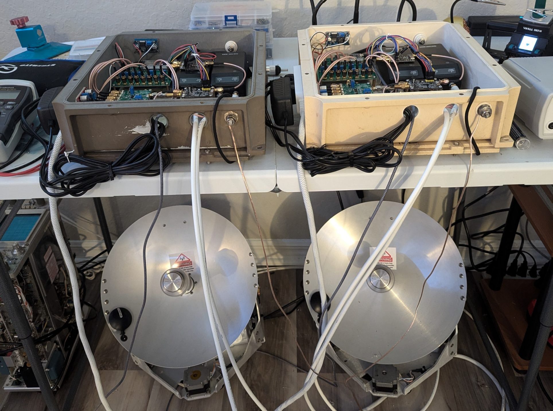
Complete Hardware
PXL_20260626_190956305
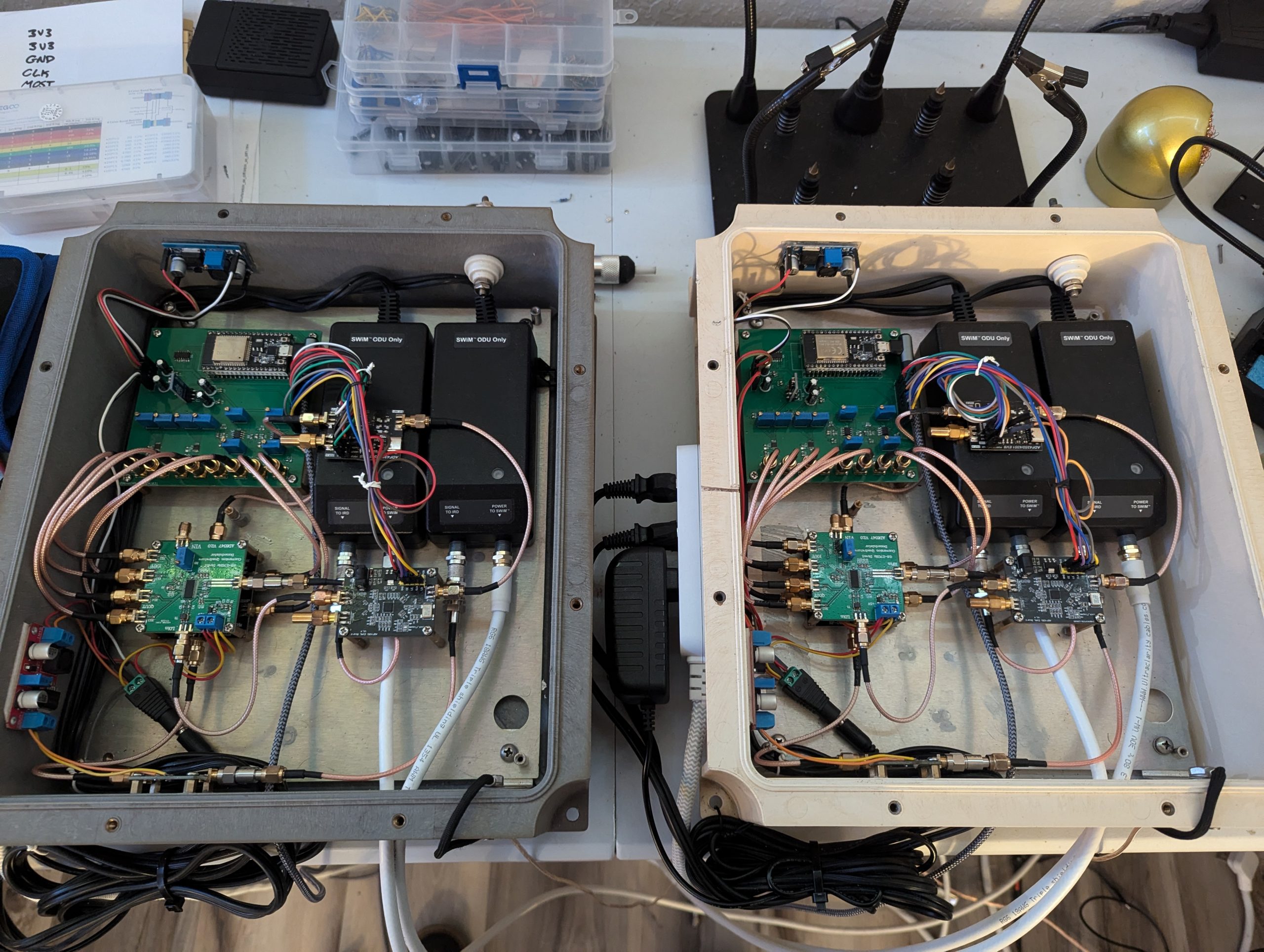
Both Modems
