
Single sideband AM Radio Modulation and Demodulation
Building An SSB Transceiver
A custom single-sideband transceiver covering 2-24 MHz, using mostly off the shelf modules.

How I Began
In January 2025, I decided to stave off some latent existential dread by constructing a SSB transceiver of my own design. This is a project I had been contemplating for some time as I have some experience with repairs and testing of marine SSB radios through my work.
I decided assemble it as much as possible from off-the-shelf modules. Surprisingly, most were available off Amazon with short shipping times. This approach gave me the flexibility to experiment and enabled me to design and test things in parallel, which for someone with ADHD and a desire for instant gratification, feels better than producing a precise, thoroughly reviewed design before I start ordering parts.
The following will pages will discuss the theory of opperation, expounding on the included system block diagram, explain my design methodology, and the results from testing. In an effort to remain off the radar of the FCC all transmission testing was done into a dummy load.
If I get to a point in this project where I am fully satisfied with my design I may design and order boards to create a more professional result. Almost all the modules I am using are pretty simple in design, most just consisting of a single specialized IC and associated decoupling caps, so migrating the design from my rats nest of modules and SMA patch cables to a single custom circuit board would be conceptually pretty simple, if time consuming.
Discussion of Theory
A SSB or single-sideband radio is a type of AM radio where only one of the sidebands is transmitted while ignoring the carrier and complementary sideband. This results in a dramatic improvement in transmit power efficiency. In the marine field, which is my only exposure to these outside the classroom, they usually transmit and receive 2 – 24 MHz range. This relatively low frequency naturally requires lengthy antennas. In practical installations on vessels automatic antenna tuners are often used to perform impedance matching between an imprecise and often too short antenna and the transceiver over a range of frequencies. Due to all this complexity and the long antennas required, these days marine SSB radios are really only found on commercial vessels in the possession of dedicated hobbyists. My radio will not be nearly as ambitious as anything sold by companies like Icom or Furuno. I seek at first just to demonstrate a sound understanding of the theory and perform satisfactory modulation and demodulation of signals over my desired frequency range. The actual output amplifier is a bit of an afterthought, and my initial testing will be done without it and with a transmitted signal power of just 30 dBm.
SSB Block Diagram
System Architecture
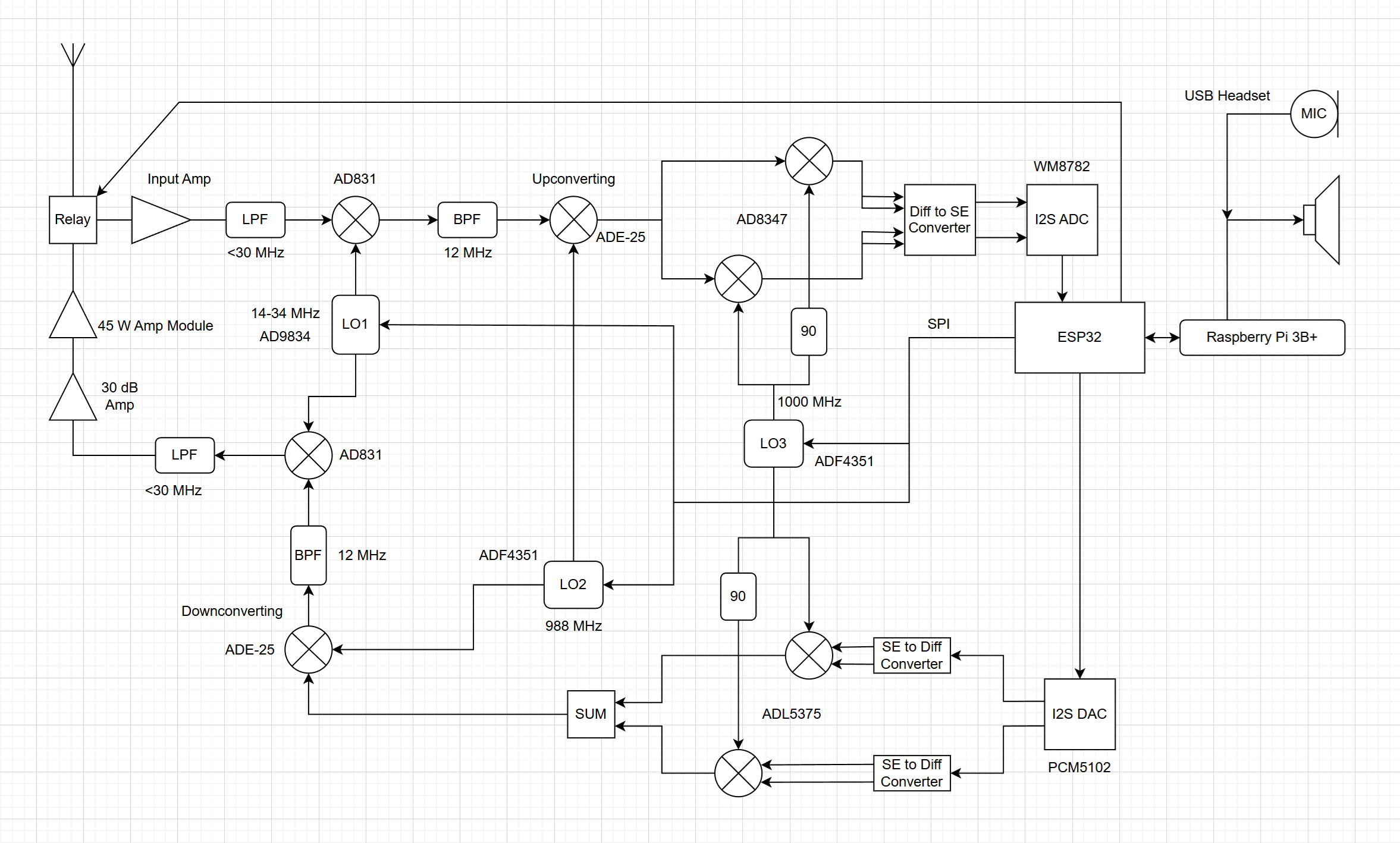
Now I should explain the basic block diagram architecture of my design. Because I am working with modules, the block diagram closely correlates to my actual physical layout. This is a partially software defined design and relies on the combination of a Raspberry Pi 3 to provide an interface and handle DSP tasks, and an ESP32 to run low level firmware and interface with my programmable local oscillators, ADCs, and DACs.
I am using an IQ phasing technique for sideband suppression. This requires the Pi to take a mono audio signal and perform a Hilbert transform to produce a two channeled digital baseband signal to pass along to the ESP32 so it can send it via the I2S bus to my DAC. The rest of the modulation and frequency shifting can then be done in hardware. A complementary receiver block then does the reverse, with an ADC sampling two baseband signals, sending them over I2S to the ESP32, and then back along to the Pi for demodulation in code back into a single coherent audio signal.
The actual modulation and demodulation is done via an ADL5375 QAM modulator module and an AD8347 demodulator module. These internally produce the 90 degree shift to one half of their local oscillator input to the mixers which when combined with the 90 degree shift to the input Q phase produces the single sideband output. The problem is that the minimum frequency these chips are designed to deal with is 400 and 800 MHz respectively. These modules are really intended for cellular applications but I am dealing with single digit and double digit MHz frequencies here. I did some research to try and find modules, or even individual chips that could do QAM modulation in my desired range, but couldn’t find anything that didn’t cost hundreds of dollars. Beside that fact, I just happened to have two spare modules left over from my KU-band QAM modem project. So I decided to just use an additional mixer stage to shift up the frequencies of the transmitted and received signals to be within the range that these modules can handle. This feels wrong, but I can’t find any actual issues with this approach.
To summarize the RF section of this project: The received signal from the antenna (after amplification) is sent through a low pass filter that blocks any signals above 25 Mhz for image suppression, it then enters an AD831 active mixer that mixes it with an adjustable local oscillator frequency of 14-36 MHz. This high side produces the first Intermediate Frequency of 12 MHz and covers the whole input range of 2-24 MHz. The image frequency range produced from this local oscillator range would be 26-38 MHZ, hence the 25 MHz low pass filter for image suppression. This first mixer is passive, so there is a lot of loss here. After passing through a 12MHz band pass filter it is further upshifted on the low side by an active ADE-25 mixer. This second IF generation with a LO frequency of 988 MHz is done solely so that the IF is at a level compatible with the QAM modulator and demodulator boards. These two boards then receive the same 1000 MHz local oscillator input for shifting the signal back down to baseband. The 988 and 1000 MHz clocks are produced by two ADF4351 modules which have fixed frequencies and power levels written to them via SPI upon startup. Tuning is done by varying the frequency produced by a AD9834 Local Oscillator module. On the transmission path there is an additional 12 MHz bandpass filter followed by an additional 25MHX low pass filter which removes the resulting image frequency from the final mixing stage before the signal enters the output amplifier.
To clarify, the reception and transmission branches of the radio are complementary and in parallel. The four mixers and modulator/demodulator boards share the clock outputs of the three local oscillator boards. All local oscillators are controlled via SPI with shared clock and data pins, and discrete chip select and control pins. A low loss RF relay is switched by the ESP32 automatically when I begin transmitting to switch the antenna to the complementary transmit path. In practice specific marine SSB channels often have different TX and RX frequencies, but this adjustment can be done in code. When the user holds down the transmit button in the GUI that runs on the Pi the relay switches the antenna to the transmit path, and only then does the system begin modulating the audio from the USB microphone onto the signal to transmit.
A minor complication comes from the fact that the audio signal from my DAC is single ended, while for best performance my QAM modulator board needs a differential input signal. Specifically it needs a differential signal with a peak to peak voltage of no more than 1V and centered around 500 mV. This same problem exists on the complementary receiving path, where a differential signal from the QAM demodulator board must be converted back to a single ended one for the ADCs. I was able to find some modules built around the THS4351 chips that served to convert a single-ended to a differential signal, but on the other side of things I had to design small boards to convert from differential to single ended. In both cases I have manual control over gain and common mode offset, with the automatic gain control built into my modulator and demodulator chips handling the rest. At least in a laboratory setting I did not have to worry about incompatible signal levels between my DACs and modulator, or my demodulator and ADCs.
The only modules not obtainable off the shelf were the aforementioned differential to single ended converter board, the relay board to switch the antenna from the transmit to receive paths, the low pass filters needed to suppress the image frequencies from the high side mixing in the first stage, and the band pass filters for the first intermediate frequency. None of these were particularly difficult to design, I quickly ordered the boards from KiCad and assembled them myself. I have some experience in higher frequency design, but in the range I am working with here, in the tens of megahertz, lumped element design was fine.
Python Code
A single python script is lauched from the Raspberry Pi desktop and provides a GUI for confirming hardware opperation and selecting the transmitting/receiving frequency. It itegrates a cheap USB headset for audio in/out and critically performs the hilbert transform of the transmitted audio to produce two digital audio signals 90 degrees out of phase, and does the reverse for the received audio to combine two signals back into one. This consitutes the software defined portion of the modulation.
Arduino Code
The ESP32’s firmware was written in Arduino due to the wealth of available libraries and my personal familiarity. The code establishes the fixed frequencies of two of the local oscilators and dynamically adjusts the other one for tuning. It also acts as a bridge between the digital audio sent and received to the Pi via the USB UART connection and the I2S serial bus used by the DAC and ADC modules. Finally it toggles two simple GPIO pins to switch the hardware between transmission and recieiving modes.
Visual Insights into the Project
Image Gallery


